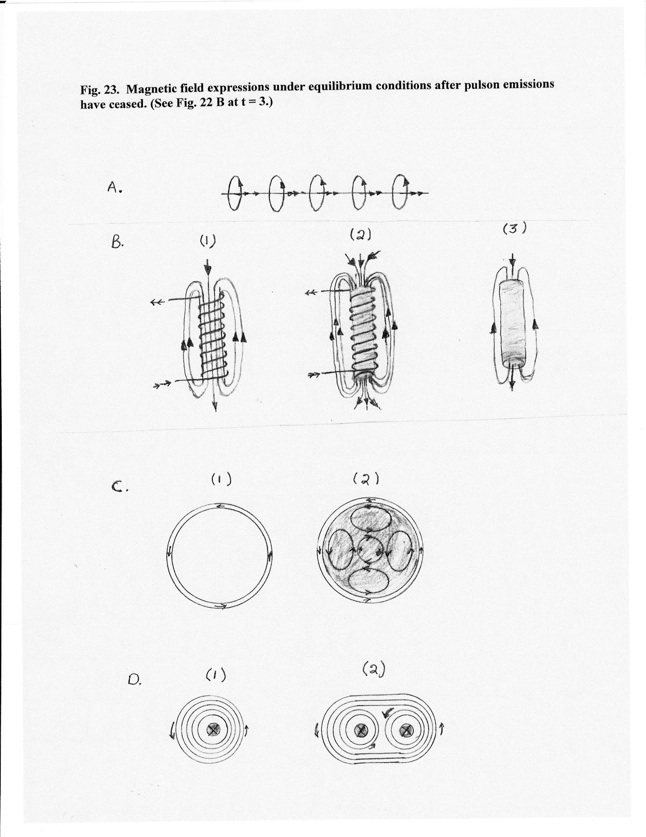
A.Magnetic field surrounding a linear conductor. () indicates direction of electron
drift. () indicates direction of the magnetic field around the conductor.
B.(1) Coil, (2) Coil with a cylindrical iron core - an enhanced magnetic field is produced, and (3) Induced magnetic condition of core after removal from coil. () indicates direction of electron drift. () indicates direction of magnetic field lines.
C.Cross sections of coil arrangements for B. (1) Direction of electron drift for B-1inside coil. (2) Direction of electrons in coil and a proposed scenario for the stable current loops induced within the iron core. The counter directional electron drift of the smaller central loop stabilizes the electron drift in the larger peripheral loops. The loop circuits are driven to an equilibrium condition by the current and the magnetic field of the coil.
D.Mutual swirl associations. (1) Magnetic field lines around conductor as depicted in (A). (2) When steady currents exist in the same direction for two parallel wires, the mutual swirl association may be created. The magnetic field of B-1 represents an equilibrated composite for mutual swirls for the coil. (Rotate the configuration of D-2 to a vertical orientation and apply to the right side of the coil.) Under conditions created in B-2 where a magnetic field passes through the core associated with the circular current of the coil, mutual swirl formations help create and stabilize the current loops that create the magnetic field of the iron core (C-2). For a ferromagnetic sample, such or similar circuits remain stable after removal from the coil. Tandem stacks associations in conjunction with the properties of the condensed matter comprising the core are proposed to facilitate this process. Such current loops are analogous to magnetic domains.