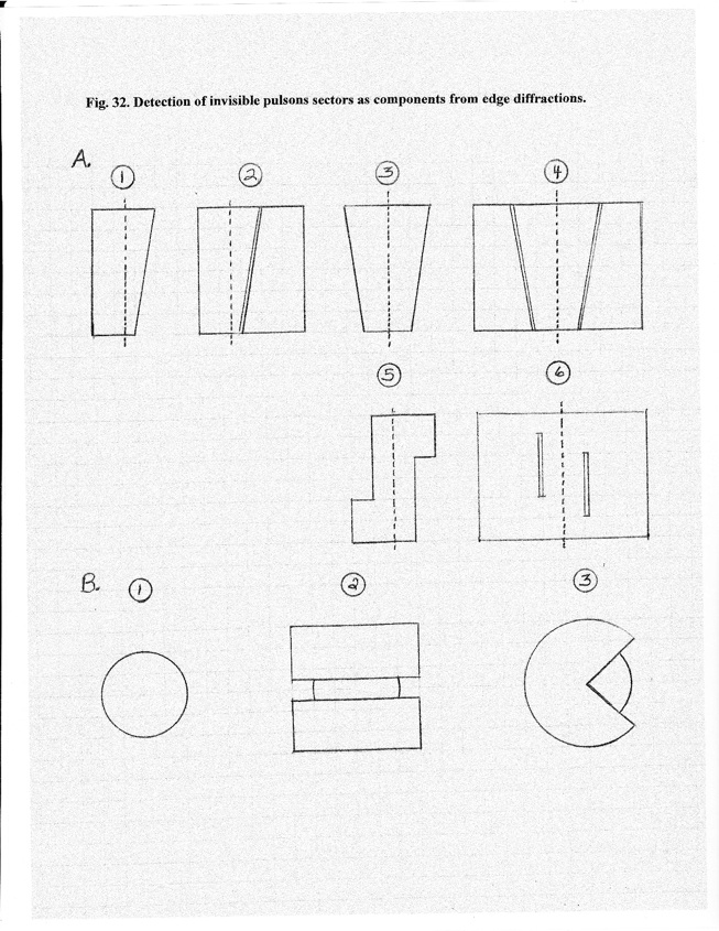
A.Elongated, straight-edge barriers exposed to point or line sources. Dashed lines indicate planes for centers of sources. 1. Control to establish illumination within the geometric shadow zone from a single diffraction edge. (See Fig. 4 and COM Fig.10.) 2. Companion experiment to A-1 with a slit. (See Fig. 9.) 3. Approach of illumination domains as a function of barrier width. 4. Companion to experiment A-3 with a slit. 5. and 6. More illustrative approaches after characterization of centerline illumination under conditions for 3 and 4. Support for invisible pulson sectors is obtained if centerline illumination occurs from dual-sided exposure before illumination from single-sided exposure has advanced a comparable distance from the edge.
B.Circular disk exposed to a centered point source. 1. Establishment of illumination and interference patterns within the geometrical shadow zone. Key reference point is the initial expression of the Poisson Spot. 2. Reduction of arc exposure while maintaining paired, coherent, secondary pulson sources (activated macrons). (See Fig. 2 E.) 3. Reduction of arc exposure by eliminating paired pulson sources. Support for invisible pulson sectors is obtained if illumination at the Poisson point appears under conditions of B-1 and B-2 before that of B-3.
C.Circular slit exposed to point source. The same protocols as for (B) are utilized. This is the arrangement utilized to produce the Bessel beam. See Fig. 7-B. C-1. When a point source is centered, the circular slit provides populations of paired twin pulsons that are temporally coherent and as for (B-1) are generated where the plane of the activating signal intersects the circular slit edges. Thus four secondary pulsons are potentially produced by each primary pulson as it interacts with the circular slit. At very narrow slit widths, less than the wavelength, an enhanced signal is obtained which should extend farther into the shadow zone than that from a single edge. (See Fig. 4 and Fig. 9.) As slit widths are increased beyond a critical width, changes in interference interactions among temporally-coherent edge pulsons as distance to the observation screen is varied should be expressed, i.e. the outside edge pulsons may interfere destructively with the inside edge pulsons. See Fig. 18. For example, it should be possible to create a dark spot from destructive interference under conditions where the Poisson spot would be observed for (B). Destructive interference at the center point where the Poisson spot occurs is not possible for a circular disk and centered point source. C-2. Companion experiment to B-2. C-3. Companion experiment to B-3. It should be possible to demonstrate interference effects of the type noted for Fig. 3-A at the center point.