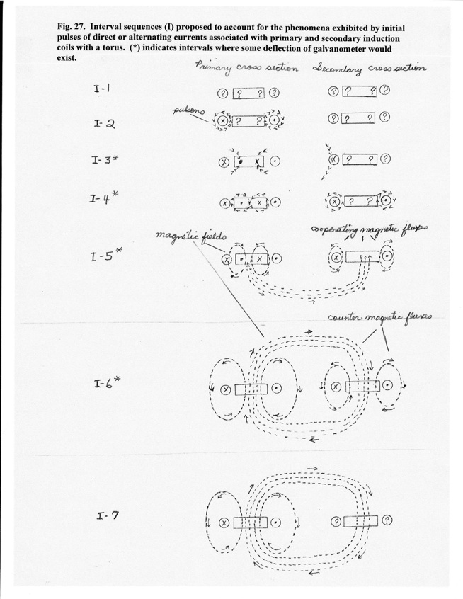
I -1. Random electron drift - no current exists. Electrons in coils and torus are in a state of random drift (?) as noted in Fig. 22 B at t = 1.
I-2. Current initiation and creations of primary pulson signals. Pulson signals (>>>) are emitted from electrons of primary coil associated with tandem stack formations at current initiation creating conditions represented in Fig. 22 B at t = 2.
I-3*. Inductions of counter currents. Pulson emissions from the primary coil induce counter currents in the iron core and secondary coil via mechanism of Fig. 22 C. This creates conditions in the primary circuit segment that produce the Einstein-de Haas effect of Fig. 24. In the secondary circuit, movement of galvanometer for Faraday’s experiment (Fig. 21 A) is initiated.
I-4*. Secondary pulson emissions. The process of pulson emissions of I-2 is repeated for the iron core of the primary and the secondary coil associated with counter current inductions. (Although I-4 is represented as a separate interval, it is superimposed temporally on current induction for the iron core and the secondary coil.)
I-5*. Transient counter magnetic fields. As the secondary pulson emissions in the torus section of the primary coil cease, the counter current in the iron core of the primary creates a magnetic field. This magnetic field tends to counter act the impetus of the secondary coil pulsons to induce a counter current in its iron core, i.e. its portion of the shared torus. The direction of the counter magnetic field of primary coil enhances the orientation of the induced current in the secondary coil. (The path of the magnetic flux from the primary to the secondary circuit is through the torus. Only the lower half of magnetic field for the torus is shown in I-5 for Fig. 27.)
I-6*. Pulson signals and counter currents have ceased. The current in the primary circuit has assumed a steady state and established a magnetic field as indicated in Fig. 23 B-2. To a lesser extent the current in the secondary coil generates a magnetic field. The decay of the current for the secondary coil is enhanced by the opposing magnetic fields of the primary and secondary circuits.
I-7. Decay of current in secondary coil. After cessation of signals from primary circuit, dissolution of tandem stacks occurs in the secondary circuit and electron drift of the secondary circuit assumes condition as indicated in Fig. 22 B at t = 1. The magnetic flux of the primary circuit dominates the torus. Galvanometer in the secondary circuit returns to zero.